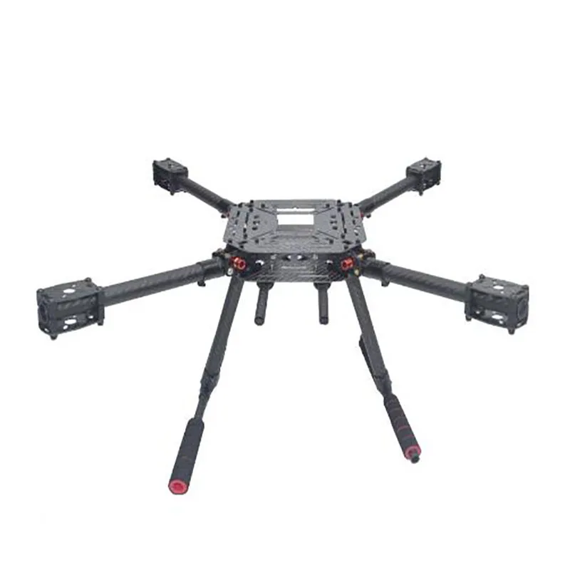
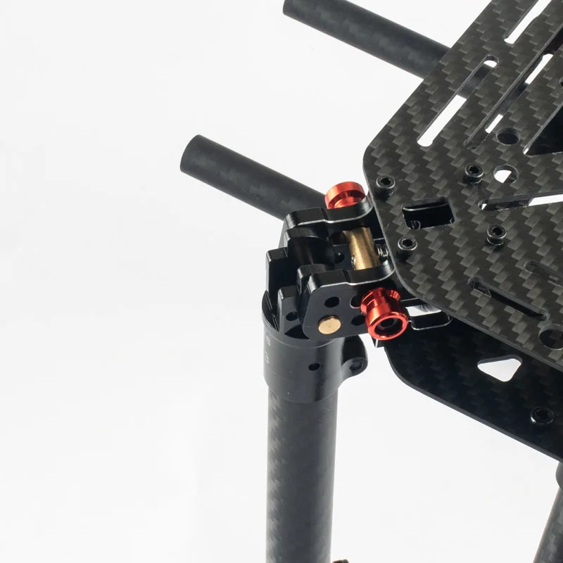
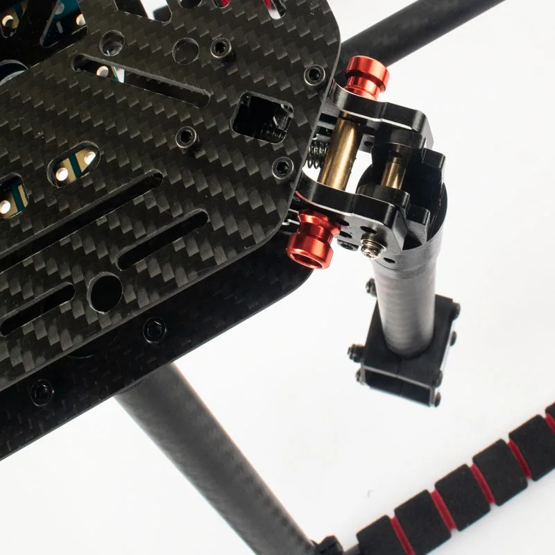
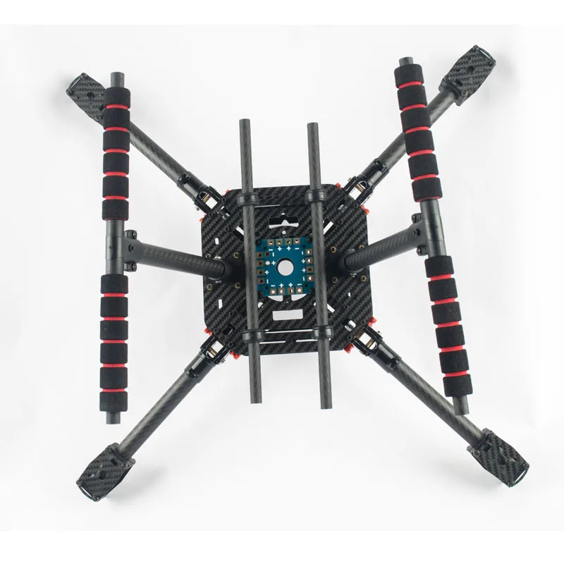
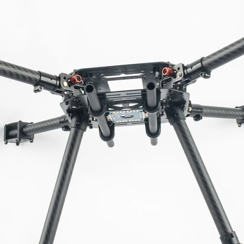
450 FRAME Wheelbase 4-Axle Frame Support 2212/2216 Motor for RC Quadcopter Drone
Please note that the screws of the motor should not touch the copper wires inside the motor, otherwise, the motor may be overloaded and burn out the motor and ESC due to idle transfer.

This article explains how to connect the ESCs, motors and propellers to a autopilot. The Pixhawk is used as an example but other autopilots are connected in a similar way.
Connect the power (+), ground (-), and signal (s) wires for each ESC to the autopilot’s main output pins by motor number. Find your frame type below to determine the assigned order of the motors.

Pixhawk Outputpins (numbered). First 4 pins are colour-coded for connecting a Quadframe
Motor order diagrams
The diagrams below show motor order for each frame type. The numbers indicate which output pin from the autopilot shoould be connected to each motor/propeller. The propeller direction is shown in green (clockwise, CW) or blue (counter-clockwise, CCW)

Legend for motor-order diagrams
Quadcopter

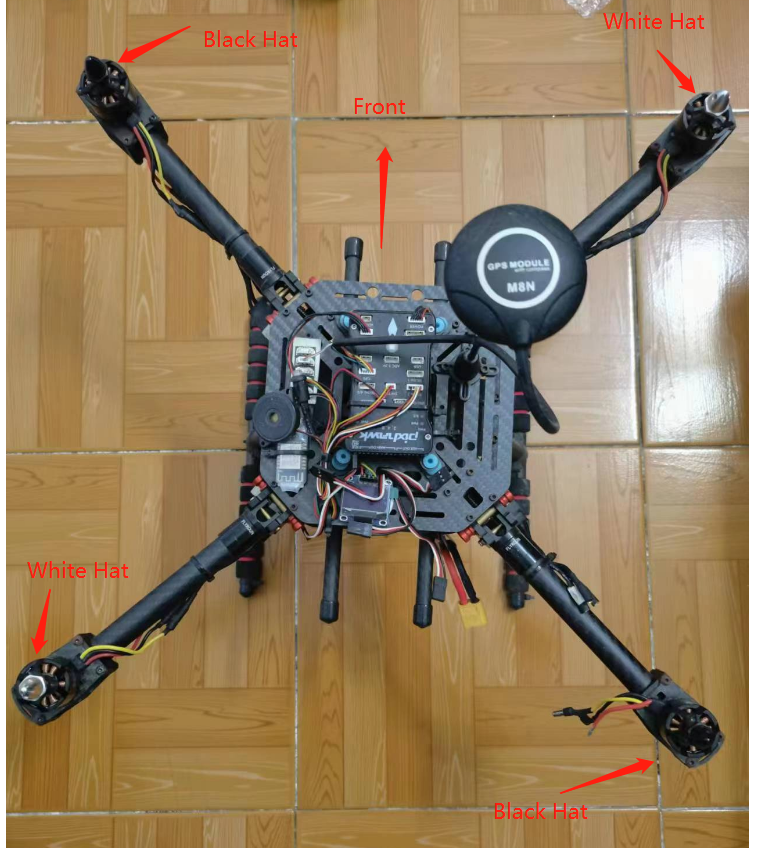
Recognizing clockwise and counterclockwise propellers

The diagrams above show two types of propellers: clockwise (called pushers) and counterclockwise (called pullers). The most reliable to recognize the correct propeller type by its shape as shown below. The thicker edge is the leading edge which moves in the direction of rotation. The trailing edge is more radical scalloped and usually thinner.
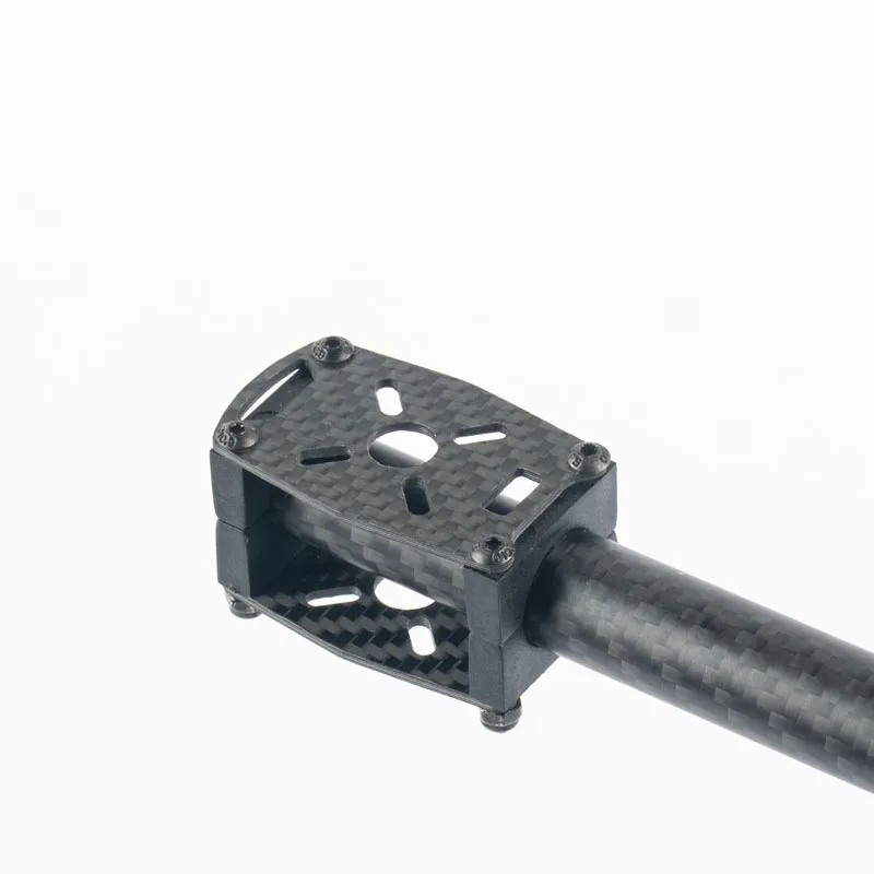
How to install Motor?