Pixracer R15
PixRacer has all the capabilities of the original Pixhawk (including version 2) and even more! It is optimized in size and has just about the right amount of inputs/outputs that allow you to switch from a full-enriched autopilot stack system (with auto landing and full navigation) to a high-performance racing platform.
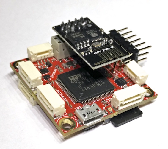
R15 has an updated accelerometer/gyro, magnetometer, and is ROHS (Lead Free). It also includes an ESP8266 for easy WiFi updates and comes with the latest Ardupilot ESP8266 firmware developed by Andrew Tridge. This new firmware has a nice web interface, MavLink2 support, and an easier way to do future updates via the web interface.
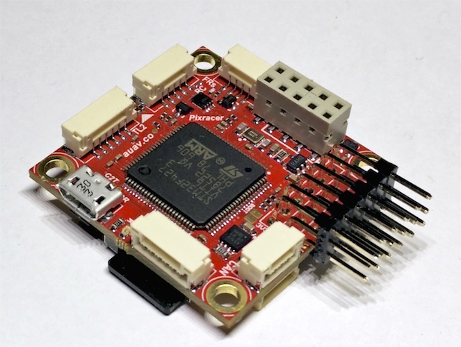
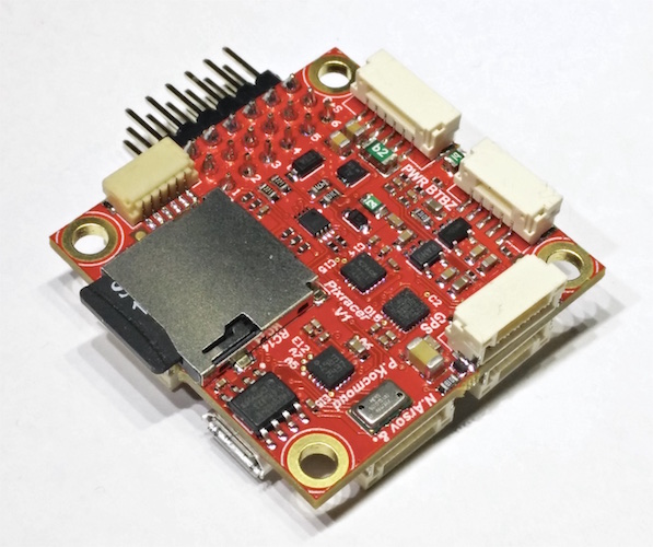
The Pixracer is the first autopilot of the FMUv4 Pixhawk generation. It comes with a small Wifi extension board.
Overview
The Pixracer is the common name for the FMUv4 generation of Pixhawk autopilots. It has been designed primarily for the demanding requirements of small multicopters, but of course can be used on planes and other vehicles which require no more than 6 pwm outputs for controlling escs and motors.
Tip
At time of writing the autopilot is still being evolved/improved. The final version may very slightly from the information provided here.
This video below provides a detailed overview of the board. Additional information can be found on pixhawk.org
Specifications
| Specifications | mRo PixRacer R15 |
| Main Processor | 32-bit STM32F427 Cortex M4 core with FPU rev.3 168 MHz |
| IO Processor | No |
| RAM | 256 KB RAM |
| Flash | 2 MB FRAM |
| Crypto / Hash Processor | No |
| Accelerometers / Gyros / Mags | 2 / 2 / 2 |
| Sensors | Invensense/TDK ICM-20602 (6DOF) Invensense/TDK MPU-9250 (9DOF) |
| Sensors – Dampened | None |
| Internal Magnetometer | AK8963 inside MPU-9250 and ST LIS3MDL |
| Barometer | MEAS MS5611 |
| Interfaces and Protocols | 5x UART (serial ports) 2x with HW flow control and GPS+I2C®]. 1x PPM sum input signal 6x PWM outputs 1x RSSI (PWM or voltage) input 1x I2C 1x SPI 1x CAN 1x JTAG (Debuging & programming interface) 8x OneShot PWM output (Configurable) 1x External microUSB port Dronecode Debug connector. WiFi Telemetry & firmware update via ESP8266 (Included). JST-GH connectors using Dronecode connector standard. Supported RC input protocols: Spektrum DSM / DSM2 / DSM-X® Satellite compatible input up to DX9 and above. Futaba S.BUS® & S.BUS2® compatible input. FRSky Telemetry port output. Graupner SUMD.Yuneec ST24. |
| Connectors | -JST GH series connectors -Servo Header -Onboard MicroUSB- 2x 5 header (Esp-01) |
| Pin Headers | Yes |
| Conformal Coating | Available |
| Extended Testing and Burn In | No |
| Custom Carrier Board Support | No |
| LED | Yes |
| Dimensions | Width: 36mm (1.42”)Length: 36mm (1.42”) |
| Weight | 10.54g (.37 oz) |
| Mounting Holes | 30mm x 30mm (1.18″x1.18″) |
| Protector Case | Optional |
| Typical Platforms | -Multirotor -Rover -Fixed-Wing -Boats -Submarines -VTOL -Automatic Tractors -Others |
Connector pin assignments
Unless noted otherwise all connectors are JST GH
TELEM1, TELEM2+OSD ports
| Pin | Signal | Volt |
|---|---|---|
| 1 (red) | VCC | +5V |
| 2 (blk) | TX (OUT) | +3.3V |
| 3 (blk) | RX (IN) | +3.3V |
| 4 (blk) | CTS (IN) | +3.3V |
| 5 (blk) | RTS (OUT) | +3.3V |
| 6 (blk) | GND | GND |
GPS port
| PIN | SIGNAL | VOLT |
|---|---|---|
| 1 (red) | VCC | +5V |
| 2 (blk) | TX (OUT) | +3.3V |
| 3 (blk) | RX (IN) | +3.3V |
| 4 (blk) | I2C1 SCL | +3.3V |
| 5 (blk) | I2C1 SDA | +3.3V |
| 6 (blk) | GND | GND |
FrSky Telemetry / SERIAL4
| PIN | SIGNAL | VOLT |
|---|---|---|
| 1 (red) | VCC | +5V |
| 2 (blk) | TX (OUT) | +3.3V |
| 3 (blk) | RX (IN) | +3.3V |
| 4 (blk) | GND | GND |
RC Input (accepts PPM / S.BUS / Spektrum / SUMD / ST24)
| PIN | SIGNAL | VOLT |
|---|---|---|
| 1 (red) | VCC | +5V |
| 2 (blk) | RC IN | +3.3V |
| 3 (blk) | RSSI IN | +3.3V |
| 4 (blk) | VDD 3V3 | +3.3V |
| 5 (blk) | GND | GND |
CAN
| PIN | SIGNAL | VOLT |
|---|---|---|
| 1 (red) | VCC | +5V |
| 2 (blk) | CAN_H | +12V |
| 3 (blk) | CAN_L | +12V |
| 4 (blk) | GND | GND |
Power
| PIN | SIGNAL | VOLT |
|---|---|---|
| 1 (red) | VCC | +5V |
| 2 (blk) | VCC | +5V |
| 3 (blk) | CURRENT | +3.3V |
| 4 (blk) | VOLTAGE | +3.3V |
| 5 (blk) | GND | GND |
| 6 (blk) | GND | GND |
Switch
| PIN | SIGNAL | VOLT |
|---|---|---|
| 1 (red) | SAFETY | GND |
| 2 (blk) | !IO_LED_SAFETY | GND |
| 3 (blk) | CURRENT | +3.3V |
| 4 (blk) | BUZZER- | – |
| 5 (blk) | BUZZER+ | – |
Debug port (JST SM06B connector)
| PIN | SIGNAL | VOLT |
|---|---|---|
| 1 (red) | VCC TARGET SHIFT | +3.3V |
| 2 (blk) | CONSOLE TX (OUT) | +3.3V |
| 3 (blk) | CONSOLE RX (IN) | +3.3V |
| 4 (blk) | SWDIO | +3.3V |
| 5 (blk) | SWCLK | +3.3V |
| 6 (blk) | GND | GND |
See also
Note
Some information and images in this page were copied from pixhawk.org, docs.px4.io